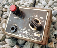
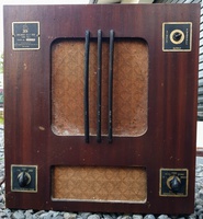
Frequency standard designed to allow technicians to align short-wave bands and was apparently originally designed for aligning the Radio Corp model 90 (Columbus and Courtenay) bandspread radio. It was connected to sets using a DA1 dummy antenna box with a rotary selector switch, one position of which was labelled SF1.
Bulletin S/42/1 - revised edition, 28 Jan 1948
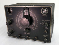
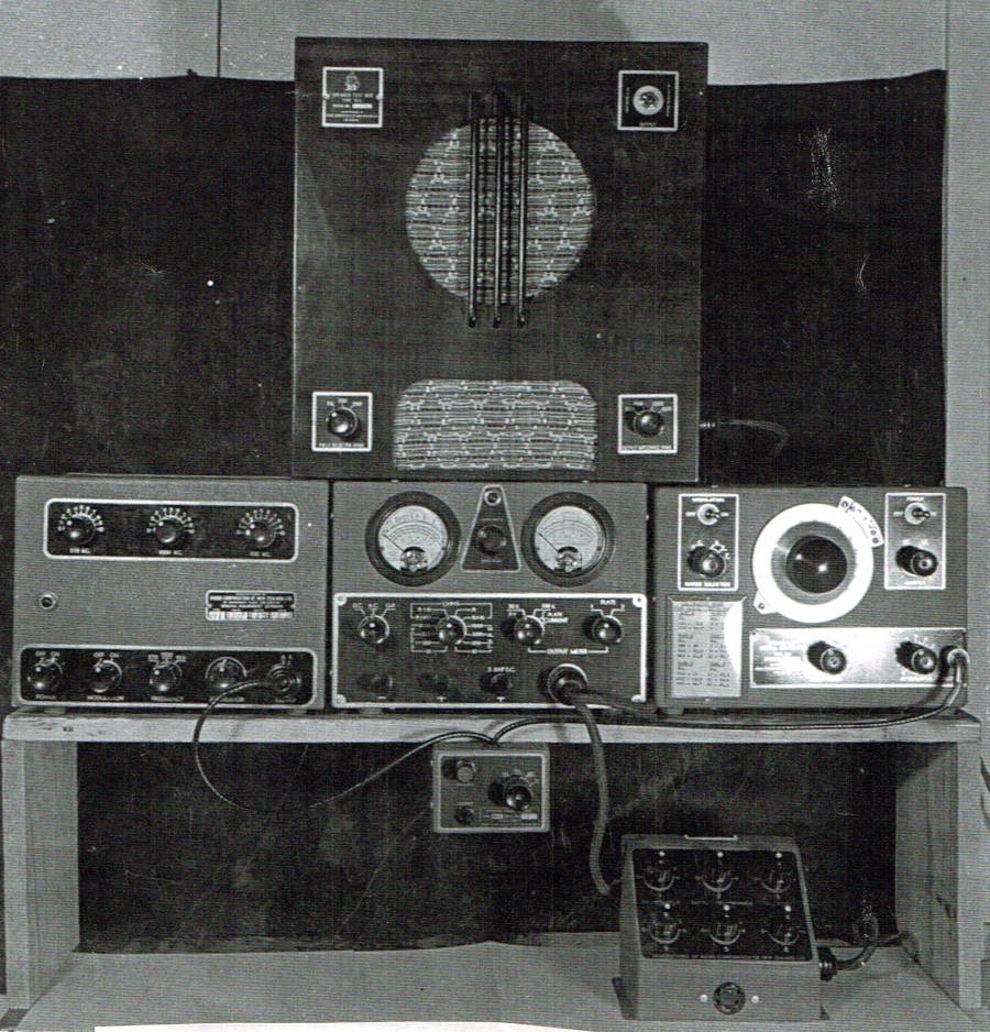
Frequency Standard Model S.F.1.
This unit consists of a temperature-compensated harmonic oscillator for operation on 230-volt AC. Fundamental frequencies of 570 kc., 1000 kc., and 100 kc. give harmonics throughout the short-wave bands covered by the (RCNZ) Model 90, which are used for calibration and alignment.
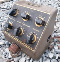
The controls consist of; 3 tuning adjustments covering the above frequencies, a power switch, modulation switch, fundamental frequency selector switch, attenuator and an R.F. outlet socket. Before using the SF1 it is essential that its frequencies be set accurately. To do this tune 2YA on the receiver under test and switch on the standard. Note: 2YA was the National Program transmitter at Titahi Bay in Wellington NZ, on 570kc/s
After allowing 10 minutes for initial warming up, switch the frequency selector to the 570 position and adjust the 570 control until the note which is heard is reduced to zero beat. The frequency is by this means adjusted to 570 kcs and harmonics will then serve as accurate frequency points for the calibration of the S.W. bands.
Switch the set under test to the 25-meter band and tune in to the signals received on 11400 and 11970 kc. Turn the receiver dial to the signal received on or near 11400 and switch the frequency selector on the SF1 to 100 kc. Tune the 100 kc control until its signal appears at 11400. Harmonics will then appear every 100 kc on the receiver scale. Tune in to the 120th harmonic of the 100 kc signal at 12000 kc, which is six divisions along the dial and switch the SF1 selector switch to 1000 kc. Adjust the 1000 kc standard control until the signal appears at this frequency, an image of 13000 kc should appear at 12090 kc.
Switch the receiver to the 16 meter band and tune in to the 1000 kc at 18000 kc, switch the standard over to 100 kc and the harmonic should appear at the same point on the receiver dial. The SF1 is now ready for operation.
When tuning the 1000 Kc. control, two signals will appear on the dial, one being the image which is 90Kc. higher in frequency.
In the case of the 100 kc control, two or three signals will appear with fundamentals above and below 100 kc. The signal that tunes with the 1000 kc signal at 12000 kc and again at 18000 kc is the correct one.
It is possible that the 100 kc fundamental may, with tube ageing or rough handling in transit, not appear on the scale - in which case it may be bought back by adjustment of the iron core in the coil. This adjustment is very critical and should only be undertaken when the operator is thoroughly conversant with the principles of operation. Any doubt as to the operation of the SF1 should be referred to the Engineering Department.
This equipment was developed by the Radio Corporation of New Zealand to furnish their Columbus Radio Centre workshops with a standardised set of test equipment.
Valves (4):
General Construction Notes for Radio Corporation of New Zealand Ltd:
The first digit of the serial number typically indicates the year of manufacture of RCNZ chassis' (although not the decade - that requires a little knowledge of the valves, construction, etc). Sets from around 1934 onwards were often (but not always) constructed in a distinctive pressed 'baking pan' style chassis, seemingly unique to RCNZ.
Model codes beginning with a 0, for example the model 051, are Osram valve versions of the model without the leading 0. Technically the 0 should be an O (for Osram), however the digit 0 was used throughout the site before this fact was discovered.
The E suffix indicates a magic eye option is fitted (in models which were available with or without, such as the model 25).
A and B suffixes appear to be simply updates to the current model, R also appears to be simply an updated model ('R'edesign, perhaps?)
P indicates either a permanent magnet speaker version of a model which also came with an electromagnet speaker (the model 26 for example), or a portable model (like the model 694P). This suffix was used in the mid 50's when Radio Corp was changing over.
N and M indicated miniature valve versions of a model which started with all (or a mix, ie: model 5) of larger valves. One of these two codes may indicate a transitional mixture of octal and miniature - clarification is required.
S often indicates a stereo model. It can also indicate 'self-biased' in the transition period between back-biased and self biased sets where there were models with both methods employed (53S for example)
Finally, other suffixes and prefixes make occasional appearances in the RCNZ lineup - like the 66W (a variant of the long-running model 66) and the 75XA (a 10-valve version of the model 75 with a separate amplifier chassis).
Model nicknames are often sourced from either newspaper advertising, company literature or the NZ Radio Traders Federation official trade-in price books (Particularly Courtenay models from this publication)
In 1954, model numbering changed, to begin with the number of valves (ie: 501 - 5 valves, 1006 - 10 valves, etc) although the final 2 digits don't appear to have much significance. Middle digits of 5 (portable) or 6 (mantle, including clock radio) are used on the AWA-designed plastic-cased sets.
 MENU
MENU